
Figure 1: Full Assembly
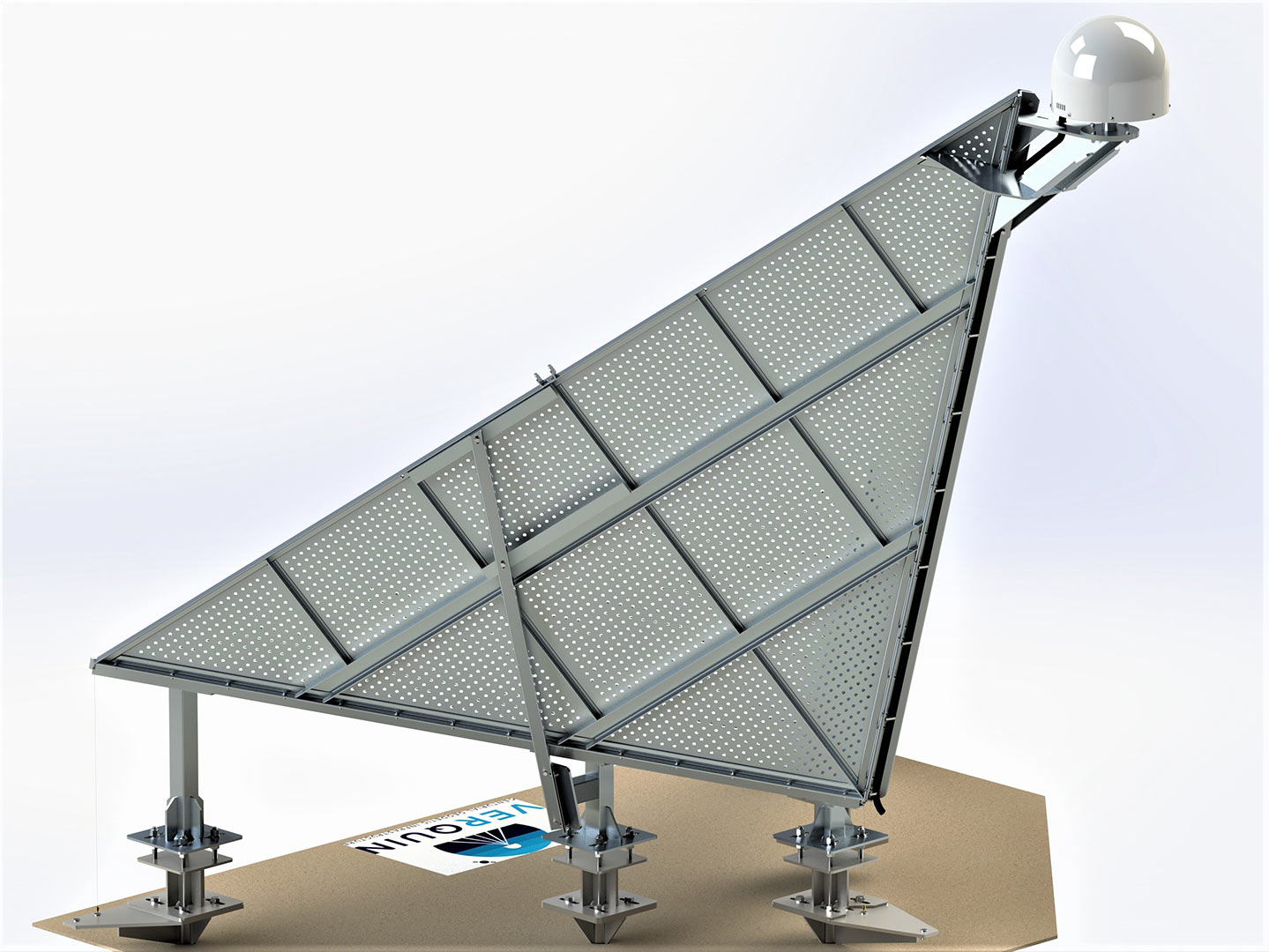
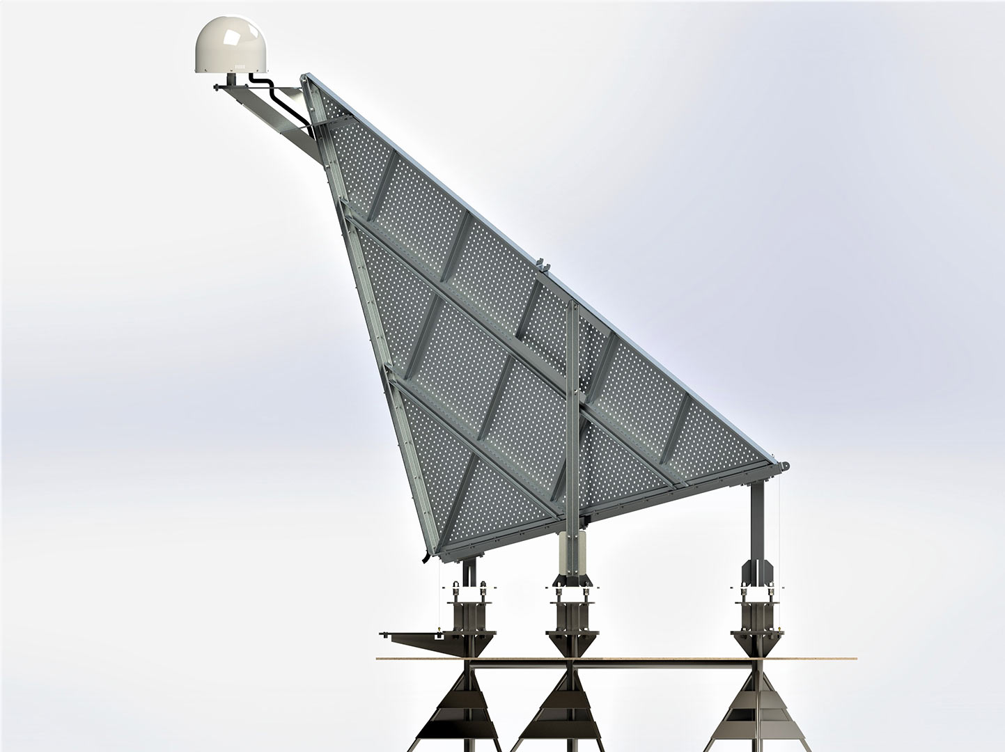
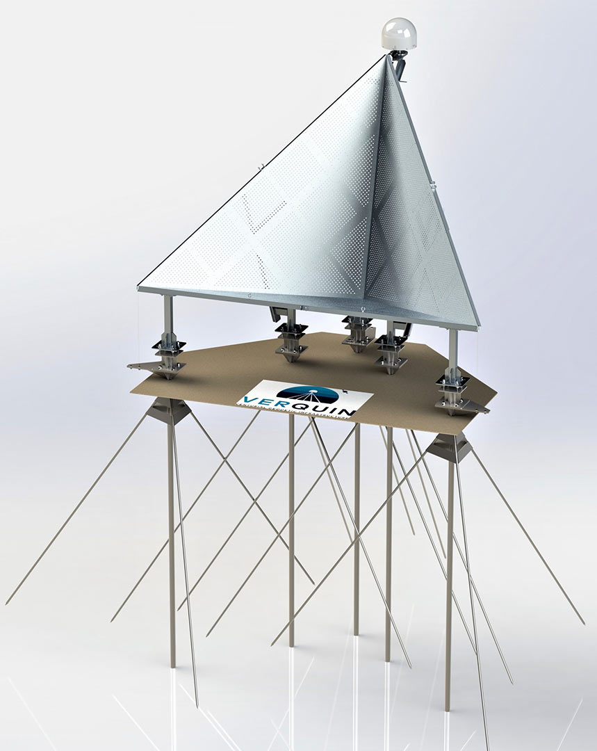
Pulling from both geodesy and traditional style survey science, the Funderpins are positioned at the vertices of the trihedral reflector for monitoring orientation (pitch, roll, yaw), deformation, and elevation change within any desired spatial reference frame.
Figure 2: Ground Control and Funderpins
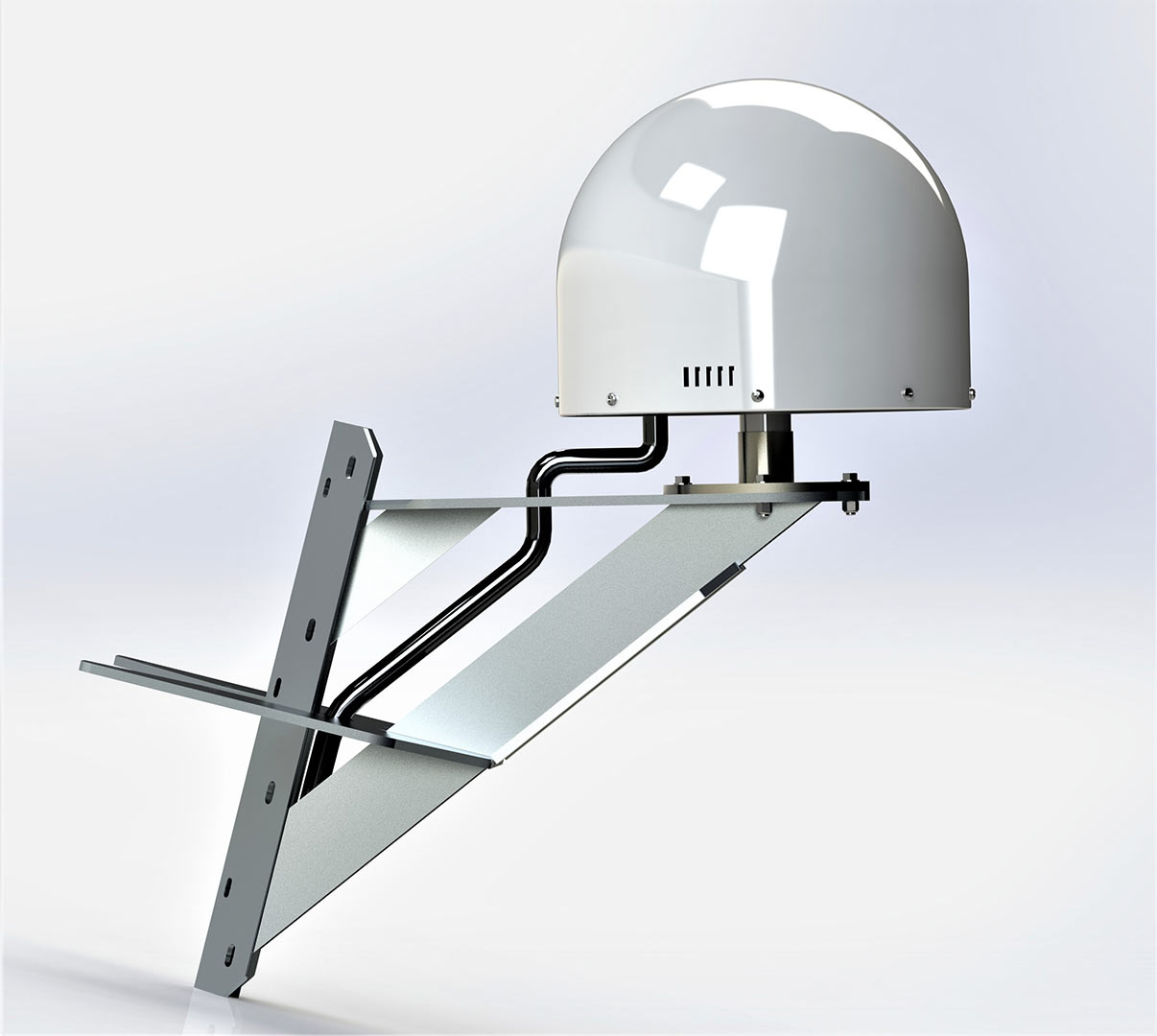
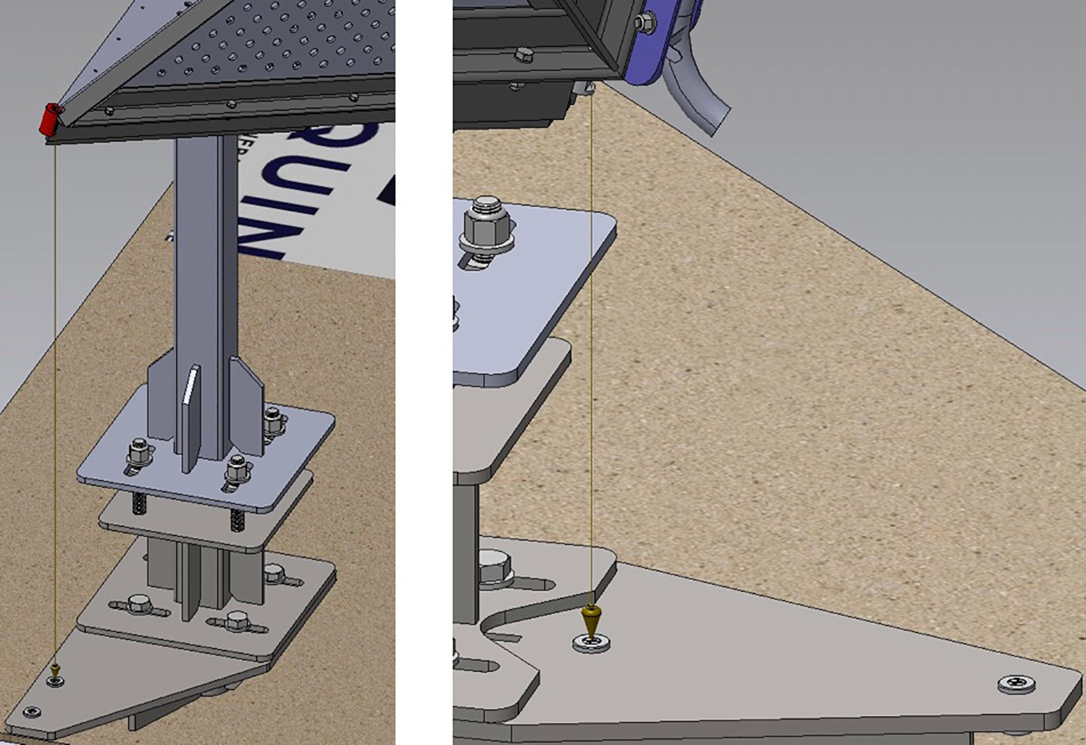 Additional stability and control of pitch, roll, and yaw, are achieved by the leveling and azimuthal control system. For continuous epoch-by-epoch measurements, position time-series development, and remote monitoring, a cGNSS antenna mount (patent pending) mated to the spine allows for individual use or can be tied directly into the machined offsets of each reflector’s respective subnetwork of survey points, to perform least squares adjustments of any reference point(s) of the reflector.
Figure 3: cGNSS mount
 Combining the science of surveying and geodesy, this is the most robustly applicable radar reflector on the market, fitting any desired spatial or temporal resolution, while providing the most geodetically accurate method of tying space-based radar measurements to a topographic surface within any spatial reference system. Solutions, Products and techniques are custom to area of deployment.
Figure 4: SAR and NISAR corner reflectors
 Benefits of deploying networks of VerQuin reflectors
- Improved accuracy and precision of repeat ground-based survey measurements
- Improved accuracy and precision of aerial and space-based measurements
- Improved accuracy and precision of interferograms and time-series analyses
- Improved accuracy and precision of 3-D surficial motion measurements
- Long-term decadal scale active aerial and space-based Cal/Val +GPS +survey control
- Real-time cGNSS monitoring
MRWLE1 Front
 This is a 2.8m NISAR HEAVY AL design with 5052-H32/6061-T6 aluminum components for the trihedral corner reflector and a 304 stainless steel fixed frame with a rotational base. A robust foundation of three interlinked geodetic-grade monuments with over 5,000 kg of concrete ballast provide stability. The entire assembly has an adjustable height 18 cm. There are Geodetic reference points at vertices for survey-grade precision measurements of orientation, geometric/geodetic position, integrating cal/val efforts across desired coordinate system and reference frame.
MRWLE1 Rotated
 The rotational base accommodates the adjustable boresight azimuth of up to 60 degrees to support multiple missions and has an adjustable tilt from 0-30 degrees. Currently, the reflector is optimized for the descending Sentinel-1 orbit, and following the much-anticipated NISAR launch, it will be repositioned to the neutral orientation for the ascending NISAR orbit.
R108W1
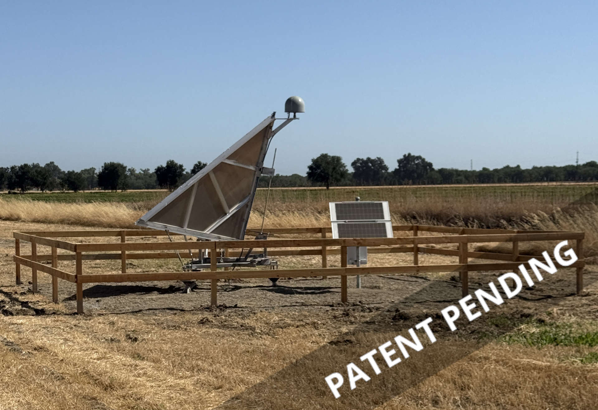
R108W1 (reflector) and 108W (cGNSS) – This site features the first deep-drilled braced monument design: a 2.8 m corner reflector with an integrated cGNSS antenna permanently mounted along the reflector’s spine. The 108W cGNSS station streams 1 Hz data in real time via the California Real-Time Network (CRTN), enabling 2–4 mm accuracy for RTK surveys of the reflector and providing epoch-by-epoch positioning for calibration/validation (cal/val) of InSAR and other geodetic techniques.
R108W1 & R108E1
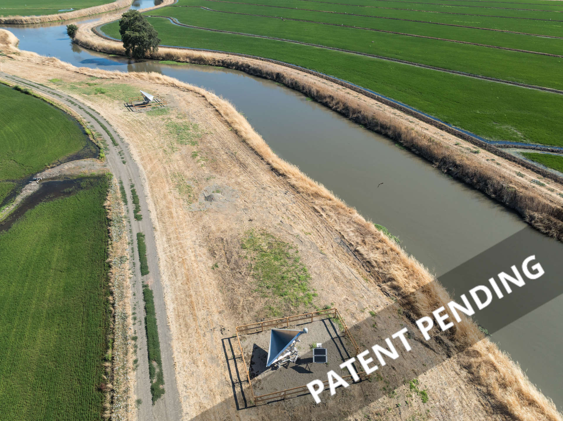
This aerial overview illustrates the separation between the paired 2.8 m NISAR L-band corner reflectors R108W1 (foreground, west) and R108E1 (top). For optimal performance with ascending and descending orbit passes, a separation of 300–600 feet is recommended between paired reflectors to minimize decorrelation effects, ensure independent sampling of the scene, and support robust cross-validation of InSAR-derived measurements.
Photo credit CA DWR 2025
NISAR Extreme
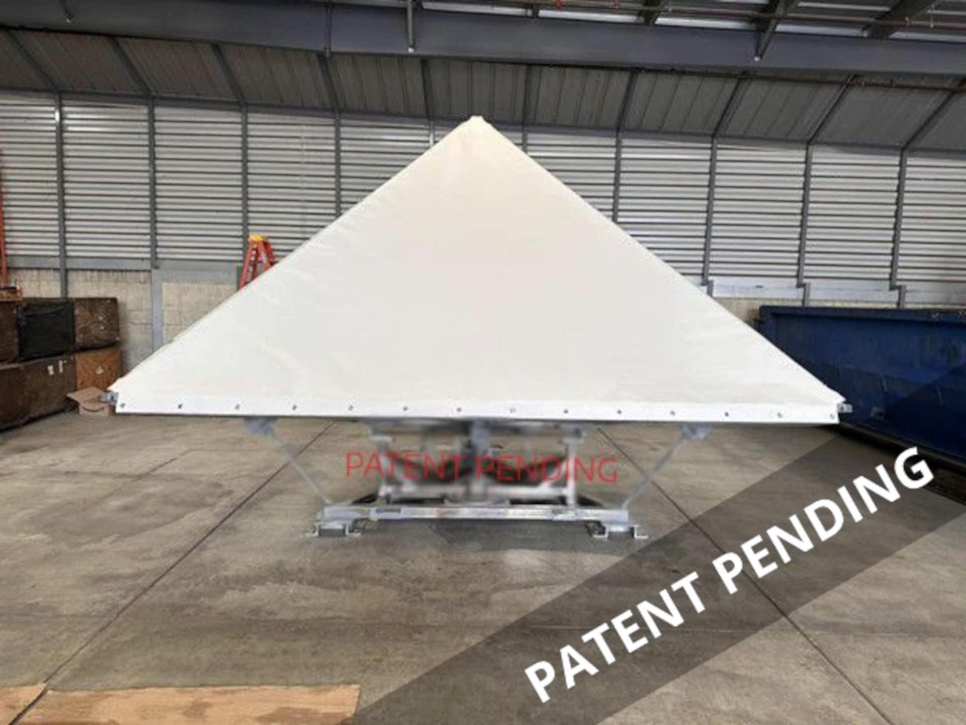
Showcased at the CEOS SAR Calibration and Validation Workshop 2025 (Vancouver, October 2025), this next-generation NISAR Extreme 2.8 m L-band trihedral corner reflector is engineered entirely from 316 stainless steel—including every structural component, fastener, and its ultra-stable rotating base—for exceptional durability and geodetic precision, with a total mass of approximately 1,000 kg. Comprehensive finite element analysis (FEA) validated the design against wind loads, structural stresses, vibration, and fatigue, confirming stability in gusts up to 350 km/h with significant safety margin. The radome covering functions as a protective ‘shock absorber,’ reducing snow accumulation, debris ingress, and environmental loading in extreme conditions. Four of these units are slated for installation in Antarctica as part of the Australian Antarctic Program, providing reliable ground control points for NISAR and other SAR missions’ radiometric and geometric calibration/validation in polar environments.
C-Band Heavy
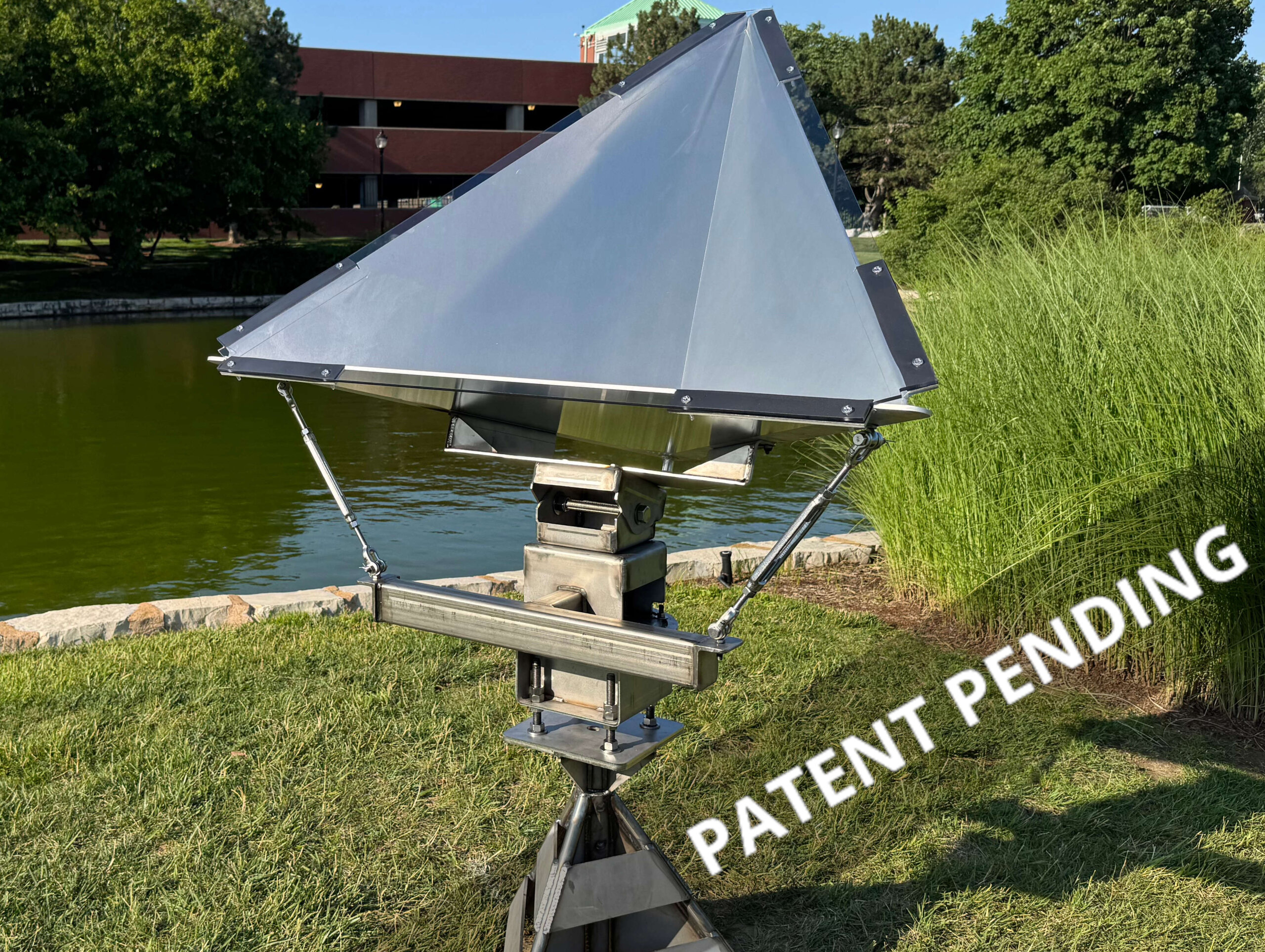
This 0.9 m C-Band Heavy trihedral corner reflector is optimized for the Sentinel-1, providing a strong, stable point target for radiometric and geometric calibration/validation. Constructed with 304 stainless steel, this geodetic-grade monument and mounting bracketry ensures sub-centimeter-level long-term positional stability and allows straightforward upsizing to 1.8 m reflectors for future needs. A MagRAM (magnetic radar absorbing material) layer beneath the radome mount points minimizes unwanted scatter and multipath, enhancing overall signal purity.